Panel Wizard
![]() The Panel Wizard plugin linear Object (PW) is a multipurpose plugin. It was originally made to draw grids "on the fly" but it get more powerful as I worked on it. It can still be used to make simple things if you simply don't use the many options. It's a kind of sequencer of lines, circles, rectangles and/or symbols.
The Panel Wizard plugin linear Object (PW) is a multipurpose plugin. It was originally made to draw grids "on the fly" but it get more powerful as I worked on it. It can still be used to make simple things if you simply don't use the many options. It's a kind of sequencer of lines, circles, rectangles and/or symbols.
Using the simplest method, you draw a line, define a sequence of intervals (there are different ways to do that) and then you generate a set of lines separated each to the other according to the sequence.
A simple example: for a page layout on a sheet layer, I would draw a PW line on the bottom side of the page, set a sequence thus: [ A*C*C*C*A ]
A is the margin, * (star) is for the column and his dimension is calculated from the length of line you draw, C is the gutter. A and C dimensions are set to 10 and 5.
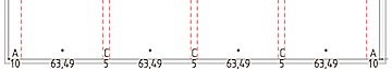
I could have written 10 directly instead of A by separating numeric values with a semicolon (;).
So the sequence is [ A*C*C*C*A ] is the same as [ 10;*C*C*C;10 ]
It could have been [ 10;*;5;*;5;*;5;*;10 ] or [a;0;5;*;C;x;c;X;10 ] but the last one are a bit confusing but possible). If I wanted to add a line in the middle of each columns, I just write two * instead of one. if you want one more column you add ‘ * C ’ in the sequence.
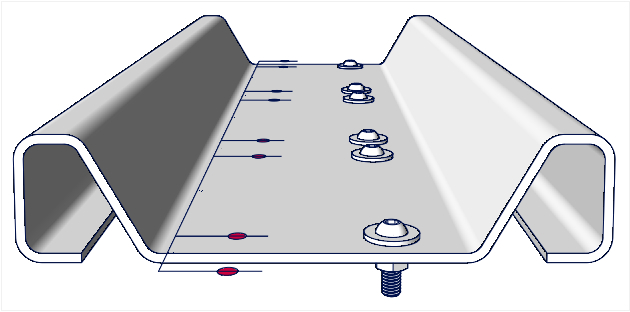
An other example: Setting the hole pattern and screws on a folded profile (drawn with Ribbon by dimensions pio).
On the left, the insert circle option is set and you get a circle on each line. If you want the hole you need to ungroup, extrude the circles and subtract the extrude from profile. On the right, the insert symbol is set and the name of the symbol defined. For a simple piece like this example is not much faster than the classic way but for a long piece with a lot of holes or many pieces that have the same pattern it can save a lot of time!. And you can modify it very quickly.
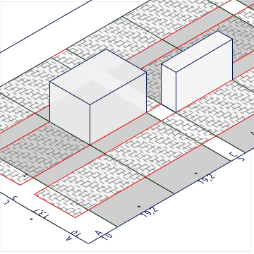
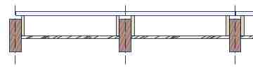
An example with rectangles: It use the insert rectangle option and copies of the same PW with various settings.
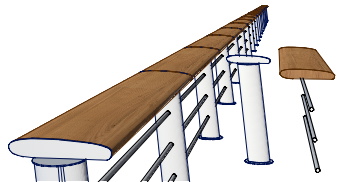
A final example with symbols: You have the option to insert two different symbols and they can be scaled (in X axis). In this case, I have a post symbol set at the A space and on other symbol (1200mm width) with the scale option, set on the star (*). Sequence 1 is 'A' and sequence 2 is '*'. The option 'Repeat seq1' and 'Seq2 between seq1' are set. The number of repeats will define the width of the symbol 2 as it's equal along the total length divided by the number of repeats (less the A spaces).
It's really interesting if you have some similar patterns that have been defined just once. You can, as with any other parametric objects, ungroup it and get each individual elements to work as usual.
how to...
Panel Wizard: (PW)
How to set a sequence?:
In the two fields "Sequence 1" and "Sequence 2" you define the sequences of spaces used as a grid. They are text fields and so they accept any characters but only some are used and the other will be discarded. you can use up to 64 characters and they are:
- A to E or a to e: These will set the space to the value set in the corresponding dimension. It also allows for the insert rectangle or symbol function that can be used to insert objects at this point only or at a '*' space.
- *, x, X, 0: These will set to a calculated space. The sum of all defined space are subtracted from the length of the RM, the rest are divided by the number of calculated spaces which are then all equal.
- Numbers: Integer or decimals (with comma or point), they must be separated by a semicolon (;) - the same is true when they are mixed with letters. 0 will be taken as calculated space.
[ A * C * C * C * A ]
=> 2 margins A, 4 columns with gutter C.
Sequence1 = [ 2 ; A ; 2 ]
Sequence2= [ * B * ]
Repeat 3x
=> [ 2 A 2 * B * 2 A 2 * B * 2 A 2 ]
[ 2;110;75;20;11;2]
Parameters are hidden when not in use.
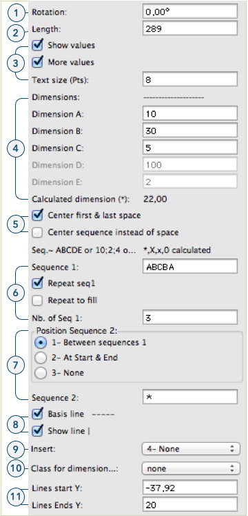
- Rotation: Like any Symbol or plug-ins it can be rotated.
- Length: The length of the grid. In some cases it has no effect to the grid ( see below). You can change this length by moving the control point or by setting a new value.
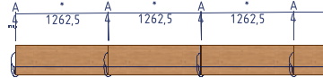
- values: Here you set if you want the value of the space to appear in the drawing. Just values will write the dimensions. More values will add the corresponding letters on top of the dimensions, the length of the PW at the end and the length of the vertical lines between the two control points. You can set the text size for the values.
- Dimensions: As soon as you set a letter (from A to E) in one sequence, the corresponding field will enable and the value set will be used for that letter. If you use anywhere in a sequence a *, x, X or a 0 (zero), the calculated dimension field will show this value. this value can negative!
- Center first & last space: You can choose to have the first and last space to be centered at start & end points. If you haven't any calculated space, this will not affect the end space (which will simply be at the end). you can also choose to have the whole sequence centered instead of the space itself.
- Sequence 1: Here you set the sequence 1 (see how to set sequence). Repeat sequences will repeat the sequence according to the options set below. Repeat to fill will calculate the number of repeats, as much as possible to fit in. If not, the number of repeats will be the one entered in field ‘Nb of Seq 1’.
- Sequence 2: hier you can decide if you use a second sequence and where it will be inserted.
- Basis line —: This draw the line you draw by inserting the PW. Actually It draws a line by space in order to have the smart points at each spaces
- Show line |: Draw the vertical lines separating each space. The lines Y coordinates are set at line start and line end Y bellow (point 9).
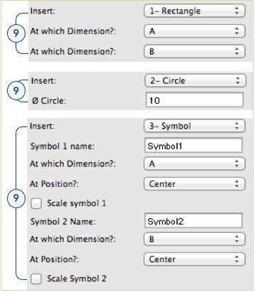
- Insert: In this part you set what you want to insert and where. It changes depending of what will be inserted. the choices are as follows:
- Rectangle: This draws rectangles the width of the defined spaces and the height and position of the vertical lines (point 8). The defined spaces must be a 'letter space' or a '*' space and are chosen using the two menus bellow.
- Circle: Insert circles at each separation (also where the vertical lines are). The diameter of the circles can be set.
- Symbol: When this option is set, symbols are placed in the space defined by the menu below the Symbol’s name. You have to give the name of a 2D, 3D or hybrid symbol that must be in the drawing (as a resource). You can decide where the symbol will be inserted in the space (start, center, end). You can insert 2 different symbols. They can also be scaled in the X axis to get the same width as the space.
- None: Insert nothing.
- Class for dimension: This will set the class for the elements that are inserted in the space defined below. For lines and circles, this will be the one at the start and end of the space.
- Lines start/end: The coordinates Y of the lines or rectangles. this can be set numerically or by moving the control points. don't put control points at the start or end of the basic line, you will not be able to move them manually (but still numerically).